Tuesday, September 7, 2021

IC555: Astable Multivibrator- LED blinking/Dancing

The 555 Timer IC can be connected either in its Monostable mode thereby producing a precision timer of a fixed time duration, or in its Bistable mode to produce a flip-flop type switching action. But we can also connect the 555 timer IC in an Astable mode to produce a very stable 555 Oscillator circuit for generating highly accurate free running waveforms whose output frequency can be adjusted by means of an externally connected RC tank circuit consisting of just two resistors and a capacitor.

Below video shows implemented circuit in Proteus design suite. You can see the LEDs connected to output pin are blinking continuously. 


In the 555 Oscillator above video, pin 2 and pin 6 are connected together allowing the circuit to re-trigger itself on each and every cycle allowing it to operate as a free running oscillator. During each cycle capacitor, C charges up through both timing resistors, R1 and R2 but discharges itself only through resistor, R2 as the other side of R2 is connected to the discharge terminal, pin 7.

Then the capacitor charges up to 2/3Vcc (the upper comparator limit) which is determined by the 0.693(R1+R2)C combination and discharges itself down to 1/3Vcc (the lower comparator limit) determined by the 0.693(R2*C) combination. This results in an output waveform whose voltage level is approximately equal to Vcc – 1.5V and whose output “ON” and “OFF” time periods are determined by the capacitor and resistors combinations. The individual times required to complete one charge and discharge cycle of the output is therefore given as:


Thursday, September 2, 2021

Python: Program for Area of Rectangle, Circle, and Square

 Below is the program which calculates the areas of Rectangle, Circle, and Square. It takes the inputs from user such as length and width for Rectangle, radius for Circle, and side of Square for Square.

Code:

length = int(input("Enter the length of the Rectangle "))

width = int(input("Enter the width of the Rectangle "))

radius = int(input("Enter radius of Circle "))

side = int(input("Enter side of the Square "))

class Area:

    def __init__(self, length, width, radius, side,):

        self.length = length

        self.width = width

        self.radius = radius

        self.side = side


    def Rect_area(self):

        rect_area = self.length*self.width

        print(f"Area of the Rectangle = {rect_area} Sq.Units")


    def Cir_area(self):

        cir_area = 3.14*self.radius**2

        print(f"Area of circle = {cir_area} Sq.Units")


    def Squ_area(self):

        squ_area = self.side**2

        print(f"Area of Square = {squ_area} Sq.Units") 


rectangle = Area(length, width, radius, side)

circle = Area(length, width, radius, side)

square = Area(length, width, radius, side)


rectangle.Rect_area()

circle.Cir_area()

square.Squ_area()

Output:

Enter the length of the Rectangle 5

Enter the width of the Rectangle 6

Enter radius of Circle 4

Enter side of the Square 7

Area of the Rectangle = 30 Sq.Units

Area of circle = 50.24 Sq.Units

Area of Square = 49 Sq.Units


Python: Finding area of rectangle

The program shown below calculates the area of the rectangle for given user inputs of length and width.

#Program:

length = int(input("Enter the length of the Rectangle "))

width = int(input("Enter the width of the Rectangle "))

class Rectangle:

    def __init__(self, length, width):

        self.length = length

        self.width = width


    def area(self):

        rect_area = self.length*self.width

        print("Area of the Rectangle = ", rect_area)


area1 = Rectangle(length, width)

area1.area()

Output:

Enter the length of the Rectangle 7

Enter the width of the Rectangle 9

Area of the Rectangle =  63

Sunday, August 29, 2021

BJT: RC coupled single stage amplifier


Common emitter RC coupled amplifier.

The common emitter RC coupled amplifier is one of the simplest and elementary transistor amplifier that can be made. Don’t expect much boom from this little circuit, the main purpose of this circuit is pre-amplification i.e to make weak signals strong enough for further processing or amplification. If designed properly, this amplifier can provide excellent signal characteristics. The circuit diagram of a single stage common emitter RC coupled amplifier using transistor is shown below.


Capacitor C1 is the input DC decoupling capacitor which blocks any DC component if present in the input signal from reaching the Q1 base. If any external DC voltage reaches the base of Q1, it will alter the biasing conditions and affects the performance of the amplifier.

R1 and R4 are the biasing resistors. This network provides the transistor Q1’s base with the necessary bias voltage to drive it into the active region. The region of operation where the transistor is completely switched of is called cut-off region and the region of operation where the transistor is completely switched ON (like a closed switch) is called saturation region. The region in between cut-off and saturation is called active region. For a transistor amplifier to function properly, it should operate in the active region. 

C3 is the output DC decoupling capacitor. It prevents any DC voltage from entering into the succeeding stage from the present stage. If this capacitor is not used the output of the amplifier (Vout) will be clamped by the DC level present at the transistors collector.

R2 is the collector resistor and R3 is the emitter resistor.

Friday, August 13, 2021

Python: Reminder Alerts program

 This program will give you Attention message for every time interval you set in time.sleep(time_in_seconds)

import os

import time

from plyer import notification


if __name__ == "__main__":

    while True:

        notification.notify(title = "ATTENTION!!!",

        message = "Take a break! It has been an hour!",

         timeout = 10)

        time.sleep(3600)


Output:


Friday, July 30, 2021

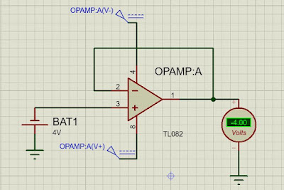
Voltage follower using Op-amp IC TL082

 What is a Voltage Follower?

A voltage follower (also known as a buffer amplifier, unity-gain amplifier, or isolation amplifier) is an op-amp circuit whose output voltage is equal to the input voltage (it “follows” the input voltage). Hence a voltage follower op-amp does not amplify the input signal and has a voltage gain of 1.

The voltage follower provides no attenuation or amplification—only buffering.

A voltage follower circuit has a very high input impedance. This characteristic makes it a popular choice in many different types of circuits that require isolation between the input and output signal.

Below figures shows implementation of Voltage follower in Proteus design suite. You can see how the output voltage is approximately equal to the given input voltages.


Sunday, July 11, 2021

Python: Anagram check program


 def anagram(s1, s2):

    #s1 and s2 are two strings which are to be checked for anagram
    s1 = s1.replace(' ', '').lower() # s1 is reaasigned with removing spaces and then made all lowercase 
    s2 = s2.replace(' ', '').lower() # s2 is reaasigned with removing spaces and then made all lowercase
    return sorted(s1) == sorted(s2)  # sorted both s1 and s2 and checked, if equal then returns True else False

print(anagram('this is right', 'is this right')) #printed True for anagram and False for not anagram

Output:
>>True

Some useful parameters

Dielectric constant  Metals have infinite Dielectric constant  As usually metals permittivity is very large than of free space hence its Die...