- Fixed-Function IC
- Full Custom ASIC
- Semi Custom ASIC
- PLD Technology
Friday, December 3, 2021
Digital design fundamentals
Thursday, September 30, 2021
BMI Calculator using Python Tkinter module
Using Python's Tkinter module, here I have implemented a BMI calculator.
BMI introduction
BMI is a measurement of a person's leanness or corpulence based on their height and weight, and is intended to quantify tissue mass. It is widely used as a general indicator of whether a person has a healthy body weight for their height. Specifically, the value obtained from the calculation of BMI is used to categorize whether a person is underweight, normal weight, overweight, or obese depending on what range the value falls between.
BMI table for adults
This is the World Health Organization's (WHO) recommended body weight based on BMI values for adults. It is used for both men and women, age 18 or older.
Category | BMI range - kg/m2 |
Severe Thinness | < 16 |
Moderate Thinness | 16 - 17 |
Mild Thinness | 17 - 18.5 |
Normal | 18.5 - 25 |
Overweight | 25 - 30 |
Obese Class I | 30 - 35 |
Obese Class II | 35 - 40 |
Obese Class III | > 40 |
from tkinter import *
def bmi_calci():
weight = float(weight_input.get())
height = float(height_input.get())
res = round((weight/(height*height))*10000, 2)
bmi_result_label.config(text=f"{res}")
window = Tk()
window.title("BMI Calculator")
window.minsize(width=250, height=150)
window.config(padx=20, pady=20)
weight = Label(text="Weight is")
weight.grid(column=0, row=0)
height = Label(text="Height is")
height.grid(column=0, row=1)
weight_input = Entry(width=12)
weight_input.grid(column=1, row=0)
height_input = Entry(width=12)
height_input.grid(column=1, row=1)
weight_label = Label(text="KG")
weight_label.grid(column=2, row=0)
height_label = Label(text="CM")
height_label.grid(column=2, row=1)
bmi_label = Label(text="Your BMI is ")
bmi_label.grid(column=0, row=2)
bmi_result_label = Label(text="0")
bmi_result_label.grid(column=1, row=2)
bmi_unit_label = Label(text="Kg/m^2")
bmi_unit_label.grid(column=2, row=2)
calculate_button = Button(text="Calculate", command = bmi_calci)
calculate_button.grid(column=1, row=3)
window.mainloop()
Output Window:
Tuesday, September 28, 2021
DCA September 2021: Check number is "UNO" or "NOT UNO"
Following code is to check if a given positive integer input by user is UNO number or NOT UNO
For e.g. if user input is 1234 then here the sum of digits if the given number is 1+2+3+4 = 10 and then again if we sum the digits of resulting number i.e. 10 is 1+0 = 1 hence if this kind of sum of digits of a number is 1 then the number is said UNO else NOT UNO
NOT UNO e.g. 234 here sum of digits is 2+3+4 = 9, this is not equal to 1 hence it is said NOT UNO
Python Program:
num = int(input()) #takes user input
def check_uno(num):
sum_d = 0
k = 0
while num > 0:
k = num % 10
sum_d = sum_d + k
num = num // 10
if sum_d == 1 or sum_d == 10:
print("UNO")
elif (sum_d > 1 and sum_d < 10):
print("NOT UNO")
elif sum_d > 11:
b = check_uno(sum_d)
check_uno(num)
#Output:
Input = 1234 Output = UNO
Input = 12345 Output = NOT UNOInput = 345345 Output = NOT UNO
Tuesday, September 7, 2021
IC555: Astable Multivibrator- LED blinking/Dancing
The 555 Timer IC can be connected either in its Monostable mode thereby producing a precision timer of a fixed time duration, or in its Bistable mode to produce a flip-flop type switching action. But we can also connect the 555 timer IC in an Astable mode to produce a very stable 555 Oscillator circuit for generating highly accurate free running waveforms whose output frequency can be adjusted by means of an externally connected RC tank circuit consisting of just two resistors and a capacitor.
Below video shows implemented circuit in Proteus design suite. You can see the LEDs connected to output pin are blinking continuously.
In the 555 Oscillator above video, pin 2 and pin 6 are connected together allowing the circuit to re-trigger itself on each and every cycle allowing it to operate as a free running oscillator. During each cycle capacitor, C charges up through both timing resistors, R1 and R2 but discharges itself only through resistor, R2 as the other side of R2 is connected to the discharge terminal, pin 7.
Then the capacitor charges up to 2/3Vcc (the upper comparator limit) which is determined by the 0.693(R1+R2)C combination and discharges itself down to 1/3Vcc (the lower comparator limit) determined by the 0.693(R2*C) combination. This results in an output waveform whose voltage level is approximately equal to Vcc – 1.5V and whose output “ON” and “OFF” time periods are determined by the capacitor and resistors combinations. The individual times required to complete one charge and discharge cycle of the output is therefore given as:
Thursday, September 2, 2021
Python: Program for Area of Rectangle, Circle, and Square
Below is the program which calculates the areas of Rectangle, Circle, and Square. It takes the inputs from user such as length and width for Rectangle, radius for Circle, and side of Square for Square.
Code:
length = int(input("Enter the length of the Rectangle "))
width = int(input("Enter the width of the Rectangle "))
radius = int(input("Enter radius of Circle "))
side = int(input("Enter side of the Square "))
class Area:
def __init__(self, length, width, radius, side,):
self.length = length
self.width = width
self.radius = radius
self.side = side
def Rect_area(self):
rect_area = self.length*self.width
print(f"Area of the Rectangle = {rect_area} Sq.Units")
def Cir_area(self):
cir_area = 3.14*self.radius**2
print(f"Area of
circle = {cir_area} Sq.Units")
def Squ_area(self):
squ_area = self.side**2
print(f"Area of Square = {squ_area} Sq.Units")
rectangle = Area(length, width, radius, side)
circle = Area(length, width, radius, side)
square = Area(length, width, radius, side)
rectangle.Rect_area()
circle.Cir_area()
square.Squ_area()
Output:
Enter the length of the Rectangle 5
Enter the width of the Rectangle 6
Enter radius of Circle 4
Enter side of the Square 7
Area of the Rectangle = 30 Sq.Units
Area of circle = 50.24 Sq.Units
Area of Square = 49 Sq.Units
Python: Finding area of rectangle
width = int(input("Enter the width of the Rectangle "))
class Rectangle:
def __init__(self, length, width):
self.length = length
self.width = width
def area(self):
rect_area = self.length*self.width
print("Area of
the Rectangle = ", rect_area)
area1 =
Rectangle(length, width)
area1.area()
Output:
Enter the length of the Rectangle 7
Enter the width of the Rectangle 9
Area of the Rectangle = 63
Sunday, August 29, 2021
BJT: RC coupled single stage amplifier
Common emitter RC coupled amplifier.
The common emitter RC coupled amplifier is one of the simplest and elementary transistor amplifier that can be made. Don’t expect much boom from this little circuit, the main purpose of this circuit is pre-amplification i.e to make weak signals strong enough for further processing or amplification. If designed properly, this amplifier can provide excellent signal characteristics. The circuit diagram of a single stage common emitter RC coupled amplifier using transistor is shown below.
Capacitor C1 is the input DC decoupling capacitor which blocks any DC component if present in the input signal from reaching the Q1 base. If any external DC voltage reaches the base of Q1, it will alter the biasing conditions and affects the performance of the amplifier.
R1 and R4 are the biasing resistors. This network provides the transistor Q1’s base with the necessary bias voltage to drive it into the active region. The region of operation where the transistor is completely switched of is called cut-off region and the region of operation where the transistor is completely switched ON (like a closed switch) is called saturation region. The region in between cut-off and saturation is called active region. For a transistor amplifier to function properly, it should operate in the active region.
C3 is the output DC decoupling capacitor. It prevents any DC voltage from entering into the succeeding stage from the present stage. If this capacitor is not used the output of the amplifier (Vout) will be clamped by the DC level present at the transistors collector.
R2 is the collector resistor and R3 is the emitter resistor.
Friday, August 13, 2021
Python: Reminder Alerts program
This program will give you Attention message for every time interval you set in time.sleep(time_in_seconds)
import os
import time
from plyer import
notification
if __name__ == "__main__":
while
True:
notification.notify(title
= "ATTENTION!!!",
message =
"Take a break! It has been an hour!",
timeout =
10)
time.sleep(3600)
Output:
Friday, July 30, 2021
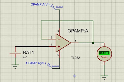
Voltage follower using Op-amp IC TL082
What is a Voltage Follower?
A voltage follower (also known as a buffer amplifier, unity-gain amplifier, or isolation amplifier) is an op-amp circuit whose output voltage is equal to the input voltage (it “follows” the input voltage). Hence a voltage follower op-amp does not amplify the input signal and has a voltage gain of 1.
The voltage follower provides no attenuation or amplification—only buffering.
A voltage follower circuit has a very high input impedance. This characteristic makes it a popular choice in many different types of circuits that require isolation between the input and output signal.
Below figures shows implementation of Voltage follower in Proteus design suite. You can see how the output voltage is approximately equal to the given input voltages.
Sunday, July 11, 2021
Python: Anagram check program
def anagram(s1, s2):
Tuesday, April 20, 2021
Python: Finding largest continuous sum in a list/array
Problem Statement:
Given a list of integers (both positive and negative) find the largest continuous sum.
e.g.
Input:
list1 = [1, 2, -1, 3, 4, 10, 10, -10, -1]
Output: 29
Solution:
Python: Find the missing element
Problem Statement: Consider array/list of non-negative integers. The second array/list is formed by shuffling the elements of the first array/list and deleting a random element. Given these two arrays/lists, find which element is missing in second array.
e.g.
list1 = [1, 2, 3, 4, 5, 6]
list2 = [2, 5, 4, 6, 3]
here missing element is 1.
Solution:
Friday, April 2, 2021
555 Timer as Monostable Multivibrator
Saturday, March 20, 2021
Python: Addition, Subtraction, Multiplication and Division using function
Program:
#Addition function
def addition(a,b):
c=a+b
print("Addition= ",c)
print("Enter two numbers")
#Subtraction function
def subtraction(a,b):
c=a-b
print("Subtraction= ",c)
#Multiplication function
def multiplication(a,b):
c=a*b
print("Multiplication= ",c)
#Division function
def division(a,b):
c=a/b
print("Division= ",c)
a=float(input())
b=float(input())
addition(a,b)
subtraction(a,b)
multiplication(a,b)
division(a,b)
Output:
Enter two numbers
8
4
Addition= 12.0
Subtraction= 4.0
Multiplication= 32.0
Division= 2.0
Python: Addition of two numbers using function
Below is a simple addition program demonstrated using function addition. This program shows you how to use function in Python
def addition(a,b): #This is funtion definitation
c=a+b
print("Addition = {}".format(c))
print("Enter two numbers to be added")
a=int(input())
b=int(input())
addition(a,b) #call the function addition() by passing two numbers a & b
Text in green are comments
Output:
Enter two numbers to be added
341
12
Addition = 353
Program for addition of two number using Python
This is a simple program for addition of two numbers using Python.
Program takes two numbers as input from the user and prints the sum as output.
#Simple Program for addition of two number without using function
print("Enter two numbers to be added")
#int can have numbers in the range -2147483648 through 2147483647
a=int(input()) #takes first number as input from user
b=int(input()) #takes second number as input from user
c=a+b #adds two numbers a & b and saves to c
print("Addition of numbers {} and {} is {}".format(a,b,c))
Text in green color shows the comments
Output:
Enter two numbers to be added
123
123
Addition of numbers 123 and 123 is 246
Saturday, January 30, 2021
Upstox Free Demat and Trading account opening
Some useful parameters
Dielectric constant Metals have infinite Dielectric constant As usually metals permittivity is very large than of free space hence its Die...
-
Building Logic gates using Op-amp 1.AND gate using op-amp:circuit diagram Check out the above circuit At inverting input of op...
-
System Design Technologies There are four design technologies: Fixed-Function IC Full Custom ASIC Semi Custom ASIC PLD Technology Fixed-Fun...